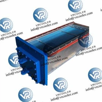
Heat Recovery Of Biogas Generator Unit
Mainstream recycling technologies and devices
Exhaust heat recovery
Waste heat boiler: produces steam at 0.4-0.6MPa and 150-170 ℃, used for industrial steam, heating, or driving lithium bromide refrigeration.
Flue gas heat exchanger: High temperature section uses finned tube/heat pipe heat exchangers to produce hot water at 90-150 ℃, while low-temperature section uses plate/shell tube preheating for boiler feedwater or domestic hot water.
Heat pipe technology: phase change self circulation, corrosion-resistant material (titanium alloy/stainless steel)+anti-corrosion coating, suitable for sulfur-containing flue gas, suitable for exhaust gas at 200-350 ℃.
Cylinder liner water waste heat recovery
Plate heat exchanger: efficient heat exchange, producing 60-80 ℃ hot water, used for heating fermentation tanks, heating or domestic hot water.
Water water heat exchanger: simple structure, suitable for small and medium-sized units, with a recovery efficiency of about 60% -75%.
Advanced Techniques
Two stage correction temperature difference power generation: High temperature exhaust gas drives the first stage power generation, and reheated cooling water drives the second stage power generation. It is equipped with phase change energy storage to stabilize the load, with an efficiency of 8% -10%.
Absorption refrigeration: using steam/hot water to drive lithium bromide units for refrigeration, achieving combined cooling, heating, and power supply.

3, System Design and Process
Pre treatment: Biogas desulfurization (H ₂ S<200ppm), dehydration (dew point<-20 ℃), pressure stabilization (5-10kPa), to reduce equipment corrosion and scaling.
Cascade recycling process
High temperature exhaust → waste heat boiler/heat pipe heat exchanger → steam production/high-temperature hot water → used for industrial steam, refrigeration or heating.
After cooling, exhaust → economizer → preheat feedwater → improve boiler efficiency.
Cylinder liner water → Plate heat exchanger → Intermediate temperature water → Used for heating fermentation tanks, domestic hot water or heating.
When there is insufficient waste heat, the distribution auxiliary heat or energy storage tank shall be used for peak shaving.
key parameters
Exhaust outlet temperature control>150 ℃ to avoid dew point corrosion; Cylinder liner water outlet temperature>50 ℃ to prevent engine overheating.
The comprehensive efficiency target of the system is greater than 85%, and an additional 0.6kWh of thermal energy is produced per cubic meter of biogas.
5, Key design points
Corrosion prevention and materials: ND steel/stainless steel+anti-corrosion coating on the exhaust side; The water side of the cylinder liner is made of titanium plate/316L stainless steel to prevent corrosion from acidic condensed water.
Optimization of heat transfer efficiency: increase the heat transfer area (fins/extended surface), increase the flow rate (Re>10 ⁴), and control the temperature difference (exhaust side Δ T ≥ 30 ℃, water side Δ T ≥ 10 ℃).
control strategy
Temperature control: exhaust outlet>150 ℃, cylinder liner water temperature 60-90 ℃.
Load tracking: When changing operating conditions, stabilize heat output through bypass valves/energy storage tanks.
Security protection: Over temperature/over pressure alarm, automatic cut-off to prevent equipment damage.