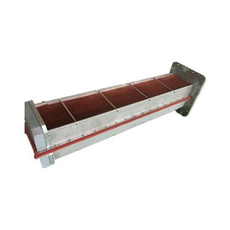
What Steps Are Required To Design A Complete Drawing Of An Air Compressor Cooler?
What Steps Are Required to Design a Complete Drawing of an Air Compressor Cooler?
The following are the main steps in designing a complete drawing of an air compressor cooler:
Determine the design requirements: including the power of the air compressor, the working pressure, the cooling medium (water or air), the cooling temperature requirements and so on.
Calculate the heat load: Calculate the heat to be emitted according to the parameters of the air compressor.
Selection of cooler type: e.g. shell and tube type, plate type, etc.
Overall layout design: determine the external dimensions of the cooler, import and export location and other general layout.
Heat exchanger tube design:
Select the appropriate tube diameter, wall thickness and material.
Determine the number of tube passes, arrangement.

Shell design:
Draw the shape and size of the shell.
Design the connection structure with heat exchanger tube.
Head design: including the shape of the head and the connection with the shell.
Tube plate design: Ensure the strength and sealing performance of the connection with the heat exchanger tube and the shell.
Folding plate or baffle design (if applicable): to guide the fluid flow and improve the efficiency of heat transfer.
Inlet and outlet pipe design: labelling dimensions and connection methods.
Internal support structure design: to ensure the stability of the cooler.
Marking dimensions and technical requirements: detailed marking of the size of each component, tolerances, materials and other technical requirements.
Drawing parts detailed drawing: such as heat exchanger tube, tube plate, head, receiver and other separate detailed drawing.
Drawing assembly drawings: show the assembly structure of the whole cooler.
Review and revision: check the accuracy, completeness and reasonableness of the drawings and make necessary revisions.
In the process of drawing drawings, it is necessary to follow the relevant drafting standards and norms to ensure that the drawings are clear, accurate and able to guide production and installation. At the same time, we should fully consider the manufacturing process, cost and maintenance convenience and other factors. For example, in the shell and tube cooler drawings, to clearly draw a sectional view of the shell, showing the arrangement of the heat exchanger tubes and the details of the connection with the tube plate, as well as the import and export of the receiver and the shell of the welded or flanged connection and other specific structures.