What Effects Do Vibration And Pitching During Ship Navigation Have On The Intercooler Of A Diesel Engine?
What effects do vibration and pitching during ship navigation have on the intercooler of a diesel engine?
Ship navigation generates continuous vibration (diesel engine operating vibration frequency: 10-50Hz, amplitude 0.1-0.5mm) and pitching/rolling (longitudinal/lateral tilt angles up to ±25°). These forces can cause cracks in intercooler welds, loosening of pipe connections, and fin deformation. Severe cases may lead to coolant leakage or intake duct blockage, disrupting normal engine operation. Three key measures-vibration-resistant design, vibration-damping installation, and component reinforcement-are required to enhance the intercooler's operational resilience and ensure stable performance under harsh sea conditions.
1. Primary Effects of Vibration and Heave on Intercoolers
Structural Damage: Prolonged vibration induces fatigue stress at welded joints between heat exchange tubes and manifolds, causing micro-cracks (particularly in copper-nickel alloy tubes with lower tensile strength at welds). Crack propagation leads to coolant leakage. Rough seas deform mounting brackets, loosen bolts, and may dislodge the intercooler entirely.
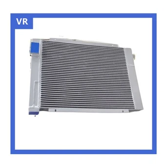
Performance Degradation: Vibration can cause fin resonance (if the fin's natural frequency aligns with the diesel engine's vibration frequency), leading to fin deformation, reduced spacing, increased air-side resistance by 10%-15%, and decreased air intake volume. Bumps cause cooling medium to slosh within heat exchange tubes, creating "air pockets" that reduce flow velocity and decrease heat transfer efficiency by 8%-12%.
Seal failure: Vibration wears out pipe joint gaskets (e.g., graphite gaskets), creating gaps in sealing surfaces and causing coolant leakage (leakage exceeding 0.5L/h impairs cooling performance). Turbulence loosens intercooler end cover bolts, compromising the seal between the end cover and core. This allows air-side and coolant-side gas mixing, further reducing heat transfer efficiency.

2. Vibration-Resistant Design Optimization
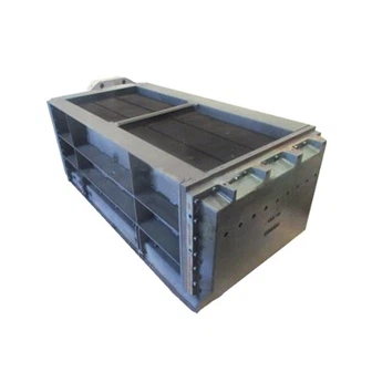
Enhanced structural rigidity: The intercooler shell employs a frame-reinforced structure (using 316L stainless steel square tubing, 50×50×5mm) welded around the shell perimeter. The frame's natural frequency is calculated via finite element analysis to ensure a ≥20% difference from the diesel engine's vibration frequency, preventing resonance. The heat exchange core adopts an integrated "tube-fin-header" design. Fins are mechanically expanded and brazed to heat exchange tubes (expansion pressure: 15-20MPa; brazing temperature: 600-650°C), achieving 30% higher joint strength than conventional welding and reducing disconnection risks from vibration.
Vibration-Resistant Design for Critical Components:
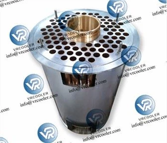
Heat exchange tubes employ a combination of thin-walled and thick-walled sections (tube wall thickness 1.5-2 mm, 0.5 mm thicker than standard heat exchange tubes) to enhance resistance to vibration fatigue. Additionally, elastic support rings (made of nitrile rubber, 5 mm thick) are installed at both ends of the heat exchange tubes to absorb vibration energy.
Pipe connections utilize bellows (stainless steel, compensation capacity ≥20mm) to prevent bending fractures caused by vibration;
Elastic sealing between end caps and core (fluororubber O-rings, 8mm cross-sectional diameter), with disc springs (50N/mm spring stiffness) fitted to end cap bolts to compensate for vibration-induced bolt loosening.
3. Vibration Damping Installation Optimization
Mounting bracket vibration damping design: The intercooler mounting bracket employs a "steel bracket + vibration damper" composite structure. The steel bracket uses Q345R marine steel plate (thickness ≥10mm), welded to the ship's hull stiffeners (weld length ≥100mm to ensure rigid connection between bracket and hull). Four rubber vibration isolators (JGD shear-type isolators with rated load matching the intercooler weight and ≥85% damping efficiency) are installed between the bracket and intercooler. Isolators are symmetrically positioned relative to the intercooler's center of gravity to ensure uniform force distribution.
Installation Location and Precision Control:
Prioritize installing the intercooler in areas with minimal engine vibration (e.g., upper engine room platforms, side walls distant from the main engine), avoiding direct installation near the main engine base (areas with vibration acceleration exceeding 10 m/s²).
Use a spirit level during installation to ensure intercooler levelness error ≤0.3° (both longitudinally and transversely), preventing uneven coolant distribution due to tilt.
Perform penetrant testing on welds between brackets and the hull to ensure no welding defects; After installation, tighten all bolts to the specified torque (50-60 N·m for M16 bolts) using a torque wrench, and apply anti-loosening adhesive (e.g., Loctite 243) to bolt heads to prevent vibration-induced loosening.