How To Ensure Heat Transfer Efficiency Of Custom Marine Box Coolers
How to Ensure Heat Transfer Efficiency of Custom Marine Box Coolers
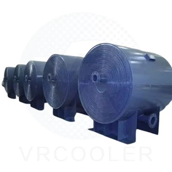
Maintaining stable and high heat transfer efficiency is core to reliable operation of custom marine box coolers. Efficiency loss mainly stems from improper design, material selection, flow disorder, marine fouling, corrosion and unreasonable installation. Comprehensive control covering design, material, structure, installation, operation and maintenance can effectively guarantee optimal heat exchange performance.
1. Optimize Customized Thermal Design Matching Vessel Actual Working Conditions
Accurate thermal calculation lays the foundation of guaranteed heat transfer efficiency. Design must be fully tailored to vessel sea chest structure, sailing status and heat load demand.First, conduct precise heat load calculation. Collect real parameters including main engine, auxiliary engine, lube oil, jacket water and hydraulic system heat dissipation volume, distinguish peak load, rated load and anchor standby working conditions. Design the cooler heat exchange capacity with 10%~15% safety margin, avoid insufficient heat exchange area leading to over-temperature of circulating medium.Second, match sea chest flow field scientifically. According to sea chest internal size, inlet and outlet grid position, hull sailing water flow direction, reasonably arrange U-tube bundle layout, tube spacing and overall outline. Avoid dead water zone and backflow area inside the sea chest. Ensure seawater can uniformly scour all heat exchange tubes, no partial flow omission. Adopt segmented or stepped bundle design for irregular-shaped sea chest to maximize effective heat exchange coverage.Third, optimize internal medium flow circuit. Design single or multi-circuit pipeline structure based on cooling medium type and flow rate. Adopt counter-flow layout between internal hot medium and external seawater as much as possible, which effectively raises average logarithmic temperature difference and improves heat transfer driving force. Reasonably control medium flow velocity inside tubes; too low velocity causes medium layering and poor heat conduction, while excessive velocity brings sharp pressure drop and energy waste. Maintain the optimal flow speed range to form stable turbulent flow and strengthen convective heat transfer effect.
2. Select High-Quality Corrosion-Resistant Heat Transfer Materials
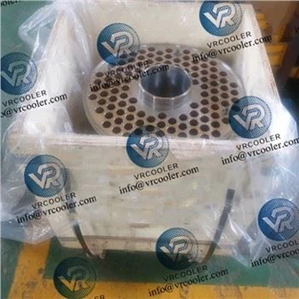
Material thermal conductivity and seawater corrosion resistance directly decide long-term heat transfer stability. Inferior materials will suffer corrosion, wall thinning and heat conduction attenuation in short service time.Priority choose high thermal conductivity marine special alloy tubes. CuNi 90/10 copper-nickel alloy tube is the mainstream choice, featuring excellent seawater corrosion resistance, anti-marine organism adhesion and stable thermal conductivity. Aluminum brass tube is applicable for medium load and mild sea water environment with good cost performance. Strict reject low-purity alloy materials with poor heat conduction performance.Supporting parts shall adopt matched anti-corrosion materials. Tube sheet uses naval brass or same-series copper-nickel alloy, keep consistent corrosion resistance with heat exchange tubes to prevent electrochemical corrosion. Internal baffles, fixed supports and connecting bonnet all adopt marine-grade anti-rust and anti-corrosion materials, avoid local corrosion damage destroying heat exchange structure.Control tube wall thickness uniformly. Moderate wall thickness balances structural strength and heat conduction speed. Over-thick tube wall increases heat transfer resistance; too thin wall is easy to be worn and corroded. Standard wall thickness matching design load ensures unobstructed heat conduction from internal hot medium to external seawater.

3. Refine Internal Structure Design to Strengthen Flow Disturbance
Reasonable structural design breaks fluid laminar boundary layer, enhances flow disturbance and substantially lifts heat transfer coefficient.Optimize U-tube arrangement form. Adopt staggered tube arrangement instead of in-line arrangement. Staggered layout makes seawater produce strong turbulence when passing through tube bundles, continuously wash away the low-temperature static water layer attached on tube surface, reduce thermal resistance on seawater side. Adjust reasonable transverse and longitudinal tube spacing, guarantee smooth water flow without excessive flow resistance.Configure flow guide and limit components. Install flow baffles and diversion plates inside sea chest and cooler body. Guide seawater to flow along preset route, prevent shortcut flow that skips most heat exchange tubes. Change flow direction moderately to enhance disturbance degree, make full use of every heat exchange surface.Optimize tube bending and connection process. Standard U-shaped bending processing avoids tube wall deformation, crack and uneven thickness caused by rough processing. Adopt reliable expansion joint or welding connection between tube and tube sheet, ensure tight combination without gap heat resistance, guarantee heat can transfer smoothly through tube wall.
4. Standardize On-site Installation and Positioning Construction
Unqualified installation distorts original flow field design, causing irreversible decline of heat transfer efficiency. Strict construction standards must be followed during hull assembly and cooler hoisting.Grasp accurate installation position. Hoist and fix the tube bundle at the designated depth inside sea chest. Keep distance from sea chest bottom, top and side walls, reserve enough seawater circulation space. Align the whole cooler with sea chest inlet and outlet grids, make incoming cold seawater first contact core heat exchange area, and heated seawater discharge out smoothly without accumulation.Control installation verticality and firmness. Keep tube bundle vertical installation, prevent inclination leading to uneven seawater scour. Use anti-vibration fixed brackets to lock the cooler firmly. Reduce vibration friction between tubes and supports during vessel navigation, avoid tube structure displacement and flow field disorder.Seal and isolate galvanic corrosion. Set insulating isolation parts between cooler and hull metal structure. Prevent stray current and potential difference from triggering electrochemical corrosion on tube surface. Avoid corrosion scale attached on tube wall increasing heat transfer resistance.
5. Strict Daily Operation Management to Stabilize Working Parameters
Standard operation mode maintains stable heat transfer temperature difference and flow state, avoiding efficiency fluctuation caused by abnormal working conditions.Stabilize internal hot medium parameters. Keep lube oil, jacket water flow rate and temperature within design rated range. Avoid sudden sharp rise of thermal load caused by engine overload operation, which exceeds instantaneous heat dissipation capacity of the cooler. Reasonably adjust circulating pump operating frequency to ensure continuous and stable medium circulation inside tubes.Adapt sailing status to utilize natural and forced convection efficiently. When vessel sails at normal speed, take full advantage of navigation impact water flow to enhance forced convection heat transfer. When anchoring and berthing, ensure unblocked natural convection up and down inside sea chest, avoid artificial blockage of inlet and outlet grids affecting cold and hot water replacement.Control external seawater access condition. Avoid long-term navigation in severely muddy and suspended-sediment dense sea area as far as possible. Reduce a large number of impurities depositing on tube surface in a short time. Timely shield sea chest inlet in severe sea conditions to prevent massive sundries from entering and blocking flow channel.
6. Regular Anti-Fouling, Anti-Corrosion Maintenance and Timely Cleaning
Marine organism attachment, sediment deposition and corrosion scale are the top factors causing heat transfer efficiency attenuation. Scheduled maintenance effectively recovers original heat exchange performance.Periodically clean heat exchange tube surface. According to sea water quality and navigation frequency, conduct surface cleaning every 3~12 months. Adopt high-pressure water washing, soft mechanical brushing or biological cleaning mode to remove barnacles, algae, sludge and sediment attached on tube outer wall. Clean internal pipeline regularly to eliminate oil dirt and scale inside tubes, reduce internal heat transfer resistance.Deploy anti-marine growth protection system. Equip ICCP impressed current cathodic protection or special anti-fouling protector. Inhibit adhesion and reproduction of marine organisms on tube surface, prolong effective service cycle of clean heat exchange surface and cut down cleaning frequency.Regularly inspect corrosion and structural damage. Check tube wall corrosion degree, welding seam tightness and support looseness during daily ship inspection. Replace severely corroded tubes timely, repair loose structural parts. Prevent local leakage and structural failure from destroying overall heat transfer balance.
7. Regular Performance Detection and Parameter Dynamic Adjustment
Establish long-term efficiency monitoring mechanism, find hidden troubles in time and optimize operating status.Install temperature and pressure monitoring sensors at inlet and outlet of cooling medium and seawater. Real-time record temperature difference, flow rate and pressure change data. Once temperature difference obviously decreases and heat dissipation effect weakens, judge efficiency loss causes and arrange targeted inspection and maintenance immediately.Compare actual operating data with design parameters. Fine-tune medium flow rate and operating parameters aiming at efficiency deviation. For aged coolers with slightly decreased performance, appropriately optimize auxiliary flow parameters to compensate heat transfer loss, keep cooling capacity meeting vessel operation demand.