How To Determine The Core Selection Parameters For Dry Coolers Based On Gas Turbine Power Ratings And Cooling Requirements?
How to determine the core selection parameters for dry coolers based on gas turbine power ratings and cooling requirements?
Dry cooler selection must precisely match the gas turbine's thermal load, exhaust temperature control targets, and operating conditions. The core approach involves establishing selection logic through three key parameters to prevent insufficient cooling or energy waste due to selection deviations, ensuring the gas turbine consistently operates within its optimal temperature range.
Core Selection Parameter Calculation
Precise Thermal Load Calculation: The cooling demand of a gas turbine primarily originates from circulating fluids (e.g., lubricating oil, hydraulic oil) and auxiliary systems (e.g., generators, bearings). The total thermal load must first be calculated using the formula: Total Thermal Load (kW) = Gas Turbine Power (MW) × Thermal Load Factor (typically 0.08–0.12). For example, a 10MW gas turbine has a total heat load of approximately 800-1200kW. The dry cooler's heat exchange capacity must cover this range while reserving a 15%-20% margin to handle high-load fluctuations (e.g., summer heat or grid peak demands).
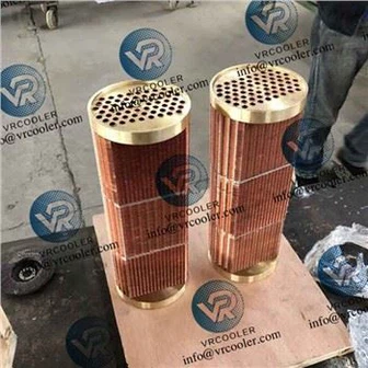
Coolant Parameter Matching: Ethylene glycol water solution (30%-50% concentration, freeze-resistant and corrosion-resistant) is commonly used as the gas turbine coolant. The inlet and outlet temperature requirements must be specified (typically inlet temperature ≤55°C, outlet temperature ≤40°C). Based on this, calculate the dry cooler's Logarithmic Mean Temperature Difference (LMTD) using the formula: LMTD = (Coolant Inlet Temperature - Air Outlet Temperature) - (Medium Outlet Temperature - Air Inlet Temperature) / ln [(Medium Inlet Temperature - Air Outlet Temperature) / (Medium Outlet Temperature - Air Inlet Temperature)]. Combine this with the heat load and heat transfer coefficient (typically 30-50 W/(m²·°C) for finned tube dry coolers) to calculate the required heat transfer area, preventing insufficient area from causing poor cooling efficiency.
Air-Side Resistance Control: Gas turbine cooling systems are sensitive to pressure loss. The air-side resistance of dry coolers must be controlled within 200-300 Pa. Resistance exceeding 350 Pa will cause a sharp increase in cooling fan energy consumption and may disrupt pressure balance in the gas turbine auxiliary systems. During selection, opt for low-resistance fin structures (e.g., corrugated fins) and validate airflow paths through fluid dynamics simulation to ensure resistance compliance.
Operating Condition-Specific Selection Adjustments
Variable Load Adaptation: For gas turbines used in peak-shaving power generation (frequent load fluctuations), dry coolers with variable flow regulation must be selected. Examples include pairing with variable-frequency cooling fans (speed range 500-1500 rpm) that adjust airflow based on real-time thermal load, preventing fan energy wastage during low-load periods.
High-Altitude/Low-Temperature Adjustments: At high altitudes, reduced air density (approximately 10% decrease per 1000m elevation) requires increasing the dry cooler's heat exchange area (by 15%-25% compared to lowland regions). Additionally, high-static-pressure fans (static pressure ≥500Pa) must be selected to ensure sufficient airflow for cooling. In low-temperature regions (winter temperatures ≤ -10°C), dry coolers with anti-freeze capabilities must be selected. For example, install electric trace heating devices (20-50W/m) on medium pipelines to prevent ethylene glycol solution from freezing and blocking the pipes.