Forced Oil And Forced Water Coolers For Transformers
Forced-Oil Coolers (FOC)
(I) Working Principle
Forced-oil coolers are based on the core logic of "forced circulation + air cooling," breaking the dependence of natural oil circulation cooling on temperature difference. By actively driving the oil flow to accelerate circulation, they significantly improve heat dissipation efficiency. According to the International Electrotechnical Commission (IEC) standard 60076-2:2011, its cooling method is coded as OFAF (Oil Forced-Air Forced), meaning internal forced oil circulation and external forced air circulation. During operation, a dedicated submersible pump extracts hot oil from the upper layer of the tank, pressurizes it, and sends it to the heat dissipation tube bundle of the cooler body. Simultaneously, the cooling fan starts, forcing air to flow rapidly over the surface of the heat dissipation tubes. Through heat conduction and convection, the heat in the hot oil is quickly transferred to the air. The cooled transformer oil has a lower temperature and increased density, flowing back to the bottom of the transformer tank through the lower connecting pipe to re-cool the core and windings, forming a complete forced oil circulation heat dissipation loop that continuously removes the heat generated during equipment operation.
(2) Structural Composition
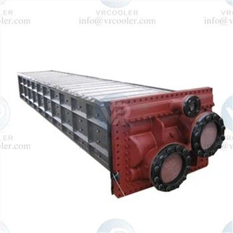
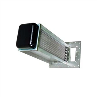
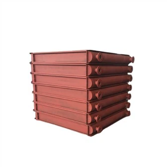
The forced oil cooler mainly consists of the cooler body, submersible pump, cooling fan, oil piping system, electrical control box, and auxiliary protection components. The cooler body typically adopts a tube-fin structure, with the heat dissipation tubes made of corrosion-resistant, high-thermal-conductivity copper or aluminum tubing, externally finned to increase the heat dissipation area. The submersible pump, as the power source for oil circulation, features high efficiency, low noise, and resistance to oil corrosion, ensuring stable oil circulation. The cooling fan is mostly an axial flow fan, controlled by a temperature sensor, starting only when the oil temperature reaches the set value, achieving energy-saving operation. The electrical control box is responsible for the overall control of the oil pump and fan's start and stop, and also integrates temperature and oil flow monitoring functions. Auxiliary protection components include oil flow indicators and differential pressure signalers, which can issue alarm signals in case of oil circulation failure or abnormal oil-water pressure differences, ensuring equipment safety.
(3) Core features and application scenarios
The core advantage of forced oil coolers is their high heat dissipation efficiency. Compared to oil immersed air cooling (ONAF) methods, their heat dissipation efficiency can be increased by more than 30%, which can meet the heat dissipation needs of large transformers under high load operation; The structure is relatively compact and can be directly mounted on the transformer body, with a small footprint and moderate maintenance workload; Strong adaptability, can adjust the heat dissipation capacity by increasing or decreasing the number of running coolers according to changes in transformer load, and achieve matching between load and heat dissipation.
Its application scenarios mainly focus on large high-voltage transformers, especially power transformers with voltage levels of 220kV and above and a capacity of 120MVA or above, which are widely used in substations, power plants, industrial plants and other scenarios. In special scenarios such as mid channel flexible straight back-to-back converter stations, low-noise forced oil coolers are also used to reduce operating noise, combined with low-noise submersible pumps, to minimize the impact of equipment operation on the surrounding environment.

Forced Water Coolers (FWC) for Transformers
(1) Working principle
The forced water cooler adopts a dual forced cooling mode of "forced oil circulation+water cooling", and its standard cooling method is coded as OFWF (Oil Forced Water Forced), which means internal oil forced circulation and external water forced circulation. The core logic is to utilize the high specific heat capacity and thermal conductivity of water compared to air, and achieve efficient heat dissipation through oil-water heat exchange. During operation, the submersible oil pump extracts the hot oil from the transformer oil tank and sends it to the oil-water heat exchanger (cooler body). At the same time, the circulating water pump pumps cooling water (mostly industrial circulating water or river water) into the other channel of the heat exchanger. The hot oil and cooling water flow in opposite directions inside the heat exchanger, and through thermal conduction, the heat in the hot oil is quickly transferred to the cooling water; The cooled transformer oil flows back to the oil tank to continue participating in the cooling cycle, while the cooling water that absorbs heat is discharged from the cooler. After subsequent cooling treatment, it can be recycled or directly discharged, forming a dual cooling circuit of "oil circulation+water circulation".
It is worth noting that during operation, it is necessary to ensure that the oil pressure is higher than the water pressure. If the heat exchange tube ruptures and water enters the transformer oil, it will cause insulation damage and trigger catastrophic accidents. Therefore, this system has extremely high requirements for sealing performance.
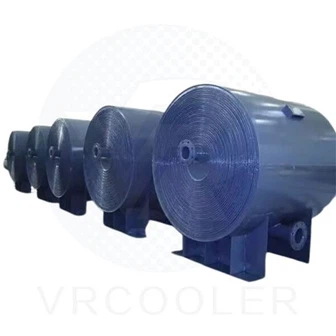
(2) Structural Composition The structure of a forced water cooler is more complex than that of a forced oil cooler, mainly consisting of the cooler body, submersible oil pump, circulating water pump, oil-water piping system, electrical control box, and safety protection devices. The cooler body (oil-water heat exchanger) comprises one oil chamber and two water chambers. The oil chamber is filled with densely packed cooling tubes, through which cooling water flows. The outer oil chamber is divided into several channels by baffles, ensuring that hot oil flows tortuously across the surface of the cooling tubes, improving heat exchange efficiency. The water chamber is divided into upper and lower chambers, with the lower water chamber further divided into two cavities, allowing the cooling water to flow bidirectionally, further enhancing heat dissipation. The oil-water piping system is equipped with valves, filters, and other components to regulate oil and water flow rates, filter impurities, and prevent pipe blockage. In addition to oil flow indicators and differential pressure signals, the safety protection devices include water level monitoring and water pressure monitoring components to monitor the operating status of the water circulation system in real time and promptly detect leaks, water shortages, and other problems.
(3) Core Features and Application Scenarios
The biggest advantage of forced water coolers is their extremely high heat dissipation efficiency. For the same cooling capacity, their volume is much smaller than forced oil coolers, they are lighter, and operate with lower noise (no fan noise), facilitating indoor installation and making them suitable for scenarios with strict noise and space requirements. Simultaneously, their heat dissipation effect is less affected by ambient temperature, maintaining stable heat dissipation performance in high-temperature environments, making them suitable for transformers operating under high load and high temperature conditions.
Their limitations mainly lie in the high system complexity, the high requirements for cooling water quality and supply stability, the need for regular maintenance of the water circulation system, replenishment of cooling water, addition of antifreeze, and cleaning of heat exchangers; and the relatively short lifespan of water-cooled systems, making it difficult to achieve the same lifespan as the transformer (typically 40 years of physical life), increasing later maintenance costs and equipment replacement frequency.
Application scenarios are mainly concentrated in areas with abundant water resources and easy drainage, such as main transformers in hydropower plant buildings; and in places with limited space and strict noise requirements, such as underground substations, substations in urban core areas, and data centers. They can also be used for cooling ultra-large capacity transformers to meet the heat dissipation needs under extreme loads.
As the core cooling equipment of transformers, forced oil coolers and forced water coolers, with their unique structures and performance, are adapted to different application scenarios and jointly provide guarantees for the safe and stable operation of transformers. Forced oil coolers have become the mainstream cooling choice for large transformers due to their simple structure, convenient maintenance, and strong adaptability; Forced water coolers play an irreplaceable role in special scenarios due to their high efficiency in heat dissipation, low noise, and compactness.
With the continuous development of the power system, cooler technology will continue to be optimized, and intelligence, efficiency, and energy conservation will become the core development direction in the future. In practical applications, it is necessary to scientifically select and standardize maintenance based on factors such as the operating requirements and installation environment of transformers, fully utilize the heat dissipation efficiency of cooling systems, extend the service life of transformers, ensure the safe, efficient, and stable operation of power systems, and provide solid support for power transmission and supply.