Aftermarket Replacement Of Guide & Thrust Bearing Oil Cooler For Steam & Gas Turbines
Aftermarket Replacement of Guide & Thrust Bearing Oil Cooler for Steam & Gas Turbines
This specification details full aftermarket replacement solutions for oil coolers serving guide bearings and thrust bearings on steam turbines, gas turbines and combined cycle turbine units. Aging, corroded, scaled or performance-degraded original coolers will be swapped with custom-matched aftermarket cooling units. The replacement restores rated heat dissipation capacity, stabilizes lubricant temperature, eliminates bearing overheating risks, and ensures continuous, safe and efficient turbine long-cycle operation.
1. Product Introduction of Aftermarket Replacement Cooler
1.1 Main Application Position
The cooler serves critical rotary support components: radial guide bearings bearing radial shaft vibration and load, and axial thrust bearings bearing axial thrust force. Both bearings generate massive friction heat during high-speed rotation; the submerged or pipeline-mounted oil cooler dissipates heat continuously to maintain qualified lubrication conditions.
1.2 Common Structural Types for Turbine Bearings
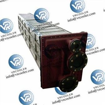
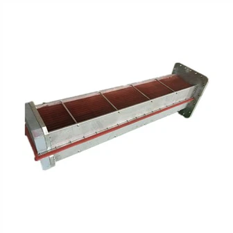
Horizontal Shell & Tube Cooler: Mainstream external type, mounted beside turbine base, suitable for large steam/gas turbine thrust-guide combined bearing system
Submerged Internal Coil Cooler: Installed inside bearing oil reservoir, compact layout, less pipeline loss
U-tube Bundle Heat Exchanger: Anti-vibration structure, adapts high-frequency vibration of turbine operation
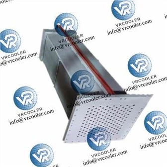
Finned Enhanced Heat Transfer Cooler: For high heat load working condition, boosts cooling efficiency in limited installation space
1.3 Aftermarket Custom Matching Features
Full dimensional interchangeability: Outer outline, mounting foot position, flange port size, installation elevation fully consistent with original equipment, no civil work or pipeline modification
Thermal performance upgrading: Recalculate actual bearing power loss and heat load, add 10%~20% safety margin to cover aging working condition deviation
Anti-vibration optimized structure: Reinforced tube bundle support, limit damping structure to resist turbine strong vibration and avoid tube abrasion fatigue
High-grade corrosion-resistant material upgrade: Improve anti-scale, anti-oil oxidation and water medium corrosion resistance compared with original old model
1.4 Standard Material Configuration
Heat exchange tube: 90/10 Cu-Ni alloy, aluminum brass, 316L stainless steel
Tube sheet: Naval brass, duplex stainless steel, high strength corrosion resistant alloy
Shell & header: Carbon steel with heavy-duty anti-rust coating, stainless steel optional
Bracket & fastener: 304/316 stainless steel, vibration fatigue resistant
2. Typical Failure Causes Demanding Aftermarket Replacement
Serious internal and external scaling: Oil dirt adheres on tube outer wall, cooling water scale accumulates inner tube wall, heat transfer resistance surges, cooling capacity drops sharply
Tube wall corrosion thinning & micro leakage: Long-term erosion of high-temperature oil and circulating cooling water causes wall attenuation, risk of oil-water mixing pollution
Vibration induced structural damage: Long time high-speed operation leads to tube bending, weld cracking, loose support and hidden failure
Aging performance attenuation: Service life expires, regular offline cleaning cannot recover original heat exchange effect
Unstable bearing temperature: Frequent high-temperature alarm affects turbine load lifting and safe power generation
3. Pre-Replacement Preparation Work
3.1 Technical Parameter Verification
Collect original cooler drawings, installation dimension, inlet/outlet flange specification, bearing rated heat load, lubricant type & flow rate, design oil temperature range, cooling water temperature and pressure parameters. Finalize customized manufacturing standards for aftermarket replacement cooler.
3.2 Unit Safety Shutdown & Isolation
Implement turbine shutdown, power lockout and mechanical safety locking procedure. Cut off lubricating oil circuit and cooling water circuit, drain residual oil and cooling water inside pipeline and old cooler. Purge internal dirt and residual medium completely.
3.3 New Aftermarket Cooler Factory Acceptance
Inspect overall appearance, tube integrity, welding quality and structural rigidity. Complete factory hydrostatic pressure test and air tightness test to confirm zero leakage. Check material certificate, dimension tolerance and performance test report meet replacement requirements.
3.4 Construction Tool & Auxiliary Material Preparation
Prepare professional hoisting equipment, disassembly tools, pressure testing device, sealing gaskets, high-strength bolts, antirust sealant and temporary connecting accessories. All construction personnel complete safety and technical disclosure.
4. Dismantling Procedure of Old Faulty Cooler
Close all isolation valves of oil and water system, confirm medium circulation fully stopped
Disconnect inlet and outlet oil pipelines and cooling water pipelines, remove connecting flanges
Dismount fixing bolts, positioning supports and damping parts of old cooler
Use special hoisting tool to fix the cooler steadily, keep balance during lifting
Lift out old cooler slowly, avoid collision with turbine base, bearing pedestal and surrounding equipment
Transport waste cooler to designated area for failure inspection and scrap disposal
Clean bearing pedestal inner cavity, pipeline interface and installation base thoroughly

5. Installation & Positioning of New Aftermarket Cooler
Hoist the new replacement cooler to installation station, adjust horizontal and vertical levelness
Align mounting holes and base positioning benchmark, place the cooler steadily in design position
Install positioning supports, anti-vibration limit and damping components, fasten bolts symmetrically and evenly
Install sealing gaskets, align oil and water flanges, connect all pipelines tightly
Check surrounding gap to ensure no friction and interference between cooler and turbine components
Conduct insulation isolation treatment to prevent galvanic corrosion and stray current damage
6. Pressure Test, Leakage Check & Flushing
Carry out hydraulic pressure test on cooling water side, test pressure 1.5 times design working pressure, hold pressure for specified duration without pressure drop and leakage
Fill lubricating oil into oil circuit, stand for observation, confirm no oil seepage at welding joints and flange connections
Implement circulating flushing for oil and water pipelines, eliminate internal sundries and residual dirt
Recheck flow channel smoothness and pipeline connection firmness
7. Commissioning & Load Verification Operation
Open cooling water and lubricating oil valves, build normal circulating working state
Start turbine no-load trial operation, real-time monitor guide bearing and thrust bearing oil inlet & outlet temperature, vibration value and medium pressure
Gradually increase unit load in stages, track cooling performance under partial load, rated load and peak load
Compare actual operating data with design index, ensure bearing oil temperature stably controlled within safe allowable range
Inspect cooler running vibration, noise and pipeline stability, eliminate abnormal operating status
8. Daily Maintenance & Post-Replacement Management
Regularly monitor temperature, pressure and flow operating parameters, capture efficiency decline early
Conduct periodic cleaning every 8–18 months to remove scale, oil sludge and surface attachments
Routinely inspect welding seam, support fastening and corrosion condition, replace vulnerable parts timely
Stabilize cooling water quality and lubricant cleanliness, slow down scaling and corrosion speed
9. Core Advantages of Aftermarket Replacement
Perfect interchangeable installation, short construction period, minimum turbine outage economic loss
Upgraded heat transfer structure and premium materials recover and exceed original design cooling efficiency
Enhanced anti-vibration and anti-corrosion ability adapts harsh turbine running environment
Effectively restrain bearing overheating, tile burning and shaft abrasion faults, prolong bearing service life
Reduce frequent overhaul and maintenance cost, improve overall operational reliability of steam & gas turbine unit
10. Application Coverage
Applicable to single shaft, double shaft steam turbines, heavy-duty industrial gas turbines, combined cycle power generation units. Widely used for old equipment renovation, sudden failure replacement, performance optimization upgrade and routine overhaul replacement of guide bearing and thrust bearing oil coolers.