Shell Tube Type Air Compressor After Cooler Design
Shell Tube Type Air Compressor After Cooler Design
Design Overview
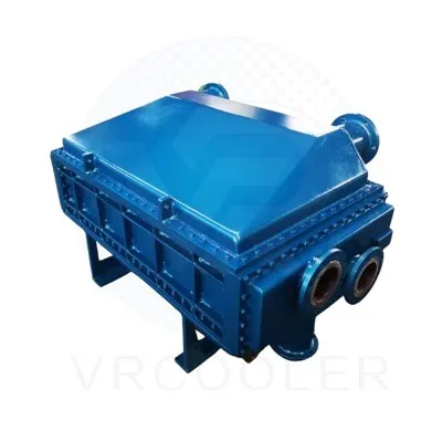
A shell-and-tube after cooler is a heat exchanger used to cool compressed air from an air compressor by transferring heat to a coolant (typically water or air). Its design involves:
Shell side: Houses the coolant (e.g., water).
Tube side: Carries the hot compressed air.
Tubesheet: Separates the shell and tube sides, securing the tubes.
Baffles: Direct coolant flow in the shell to enhance heat transfer.
Key Design Objectives:
Efficient heat transfer to reduce air temperature (e.g., from ~120°C to ≤40°C).
Pressure drop minimization for both air and coolant.
Structural integrity to withstand compressor discharge pressure (e.g., 7–15 bar).
Corrosion resistance (due to moisture in compressed air).

Structural and Operational Considerations
Corrosion Prevention:
Use anti-corrosive coatings (e.g., epoxy) for steel components.
Install moisture drains at the bottom of the shell to remove condensed water.
Thermal Expansion:
Use floating heads or expansion joints if temperature differences cause significant stress.
Maintenance:
Design for easy tube cleaning (removable tube bundle).
Include pressure gauges and thermocouples for monitoring.
Safety:
Rated for maximum compressor discharge pressure (e.g., 1.5× operating pressure).
Design Parameters and Considerations
| Parameter | Design Considerations |
|---|---|
| Fluid Properties | - Air: Inlet temperature, pressure, flow rate, moisture content. - Coolant: Type (water/air), inlet temperature, flow rate, hardness (for water). |
| Material Selection | - Tubes: Copper (good thermal conductivity), stainless steel (corrosion resistance), or titanium (for aggressive environments). - Shell: Carbon steel or stainless steel. - Tubesheets: Stainless steel or nickel alloys. |
| Tube Configuration | - Diameter: Typically 10–25 mm (smaller tubes increase surface area but may foul easily). - Length: 1–3 meters (longer tubes improve efficiency but require more space). - Layout: Triangular or square pitch (triangular allows closer spacing for higher heat transfer). |
| Baffle Design | - Spacing: Typically 0.2–1 times the shell diameter; affects coolant velocity and pressure drop. - Cut: Segmental baffles with 25–50% cut height to balance flow and heat transfer. |
| Pressure Drop Limits | - Air side: ≤5% of compressor discharge pressure (e.g., ≤0.5 bar for 10 bar systems). - Coolant side: Depends on pump capacity (e.g., ≤0.3 bar for water systems). |