

How To Design A Tube Bundle Air Compressor Aftercooler
1. Determine Design Requirements
Air Flow Rate: Know the volume of compressed air that needs to be cooled. This is usually given in cubic meters per minute or cubic feet per minute.
Inlet and Outlet Temperatures: Determine the temperature of the compressed air entering the aftercooler and the desired temperature of the air after cooling. This is crucial for calculating the heat transfer requirements.
Pressure Drop: Specify the maximum allowable pressure drop across the aftercooler. This affects the overall performance of the compressor system.
2. Select Tube Bundle Configuration
Tube Layout: Common tube layouts include in - line and staggered arrangements. Staggered layouts generally offer better heat transfer but may have a higher pressure drop.
Tube Diameter and Length: Choose an appropriate tube diameter (usually 10 - 25 mm) and length (depending on the available space and heat transfer requirements). Longer tubes can provide more heat transfer area, but may increase the pressure drop.
Number of Tubes: Calculate the number of tubes required based on the heat transfer area needed and the available space within the aftercooler shell.
3. Calculate Heat Transfer
Heat Load: Determine the amount of heat that needs to be removed from the compressed air. This is calculated using the specific heat capacity of air, the mass flow rate of air, and the temperature difference between the inlet and outlet air.
Overall Heat Transfer Coefficient: Estimate the overall heat transfer coefficient based on the type of fluid (air and cooling medium), tube material, and flow conditions. Typical values for air - to - water heat exchangers range from 50 - 200 W/(m²·K).
Heat Transfer Area: Use the heat load and the overall heat transfer coefficient to calculate the required heat transfer area. The formula is
Q=UAΔT lm, where Q is the heat load, U is the overall heat transfer coefficient, A is the heat transfer area, and ΔT lm is the log - mean temperature difference between the air and the cooling medium.
4. Design the Shell and Headers
Shell Dimensions: Determine the diameter and length of the shell based on the tube bundle configuration and the required flow area for the cooling medium. The shell should be large enough to accommodate the tube bundle and allow for proper flow of the cooling medium.
Headers: Design the inlet and outlet headers for the air and the cooling medium. The headers should be designed to distribute the fluids evenly across the tube bundle and minimize pressure drop.
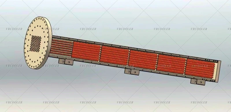
5. Select Cooling Medium and Flow Rate
Cooling Medium: Common cooling media include water, air, or a refrigerant. Water is often preferred for its high heat capacity and good heat transfer properties.
Flow Rate: Calculate the flow rate of the cooling medium required to remove the heat from the compressed air. This is based on the heat load and the specific heat capacity of the cooling medium. The flow rate should be sufficient to maintain the desired temperature of the cooling medium and ensure effective heat transfer.
6. Check for Pressure Drop
Air - Side Pressure Drop: Calculate the pressure drop of the compressed air across the tube bundle using appropriate correlations for flow through tubes and fittings. The pressure drop should be within the allowable limit specified in the design requirements.
Cooling - Medium - Side Pressure Drop: Similarly, calculate the pressure drop of the cooling medium across the aftercooler. This includes the pressure drop through the tubes, headers, and any other components in the cooling circuit.
7. Mechanical Design and Construction
Tube - to - Tube Sheet Connection: Ensure a secure and leak - proof connection between the tubes and the tube sheets. This can be achieved through welding, brazing, or using mechanical expansion joints.
Shell Construction: The shell should be designed to withstand the operating pressure and temperature of the aftercooler. It may be made of carbon steel, stainless steel, or other suitable materials depending on the corrosiveness of the fluids.
Support Structures: Provide appropriate support structures for the tube bundle and the shell to prevent vibration and ensure the stability of the aftercooler.
8. Testing and Optimization
Performance Testing: After the aftercooler is constructed, conduct performance tests to verify that it meets the design requirements. This includes measuring the air flow rate, inlet and outlet temperatures, and pressure drops across the aftercooler.
Optimization: Based on the test results, make any necessary adjustments or optimizations to the design. This may involve changing the tube bundle configuration, adjusting the flow rates of the air and the cooling medium, or improving the heat transfer surfaces.


