Factors Affecting The Performance Of Finned Tube Heat Recovery For Gas Generator
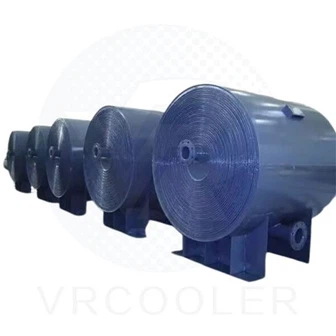
In gas generator systems, a significant amount of energy is wasted through hot exhaust gases. Installing a finned tube heat recovery system allows this waste heat to be converted into useful thermal energy, improving overall plant efficiency and reducing fuel costs. However, the performance of such systems depends on several critical design and operating factors. Understanding these factors helps ensure optimal heat recovery and long-term reliability.

1. Exhaust Gas Temperature and Flow Rate
The exhaust gas temperature and flow rate directly determine the available waste heat. Higher exhaust temperatures and larger gas volumes enable greater heat recovery potential. When exhaust gas temperature decreases, the driving force for heat transfer reduces, lowering overall performance.
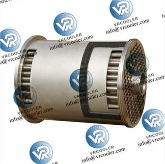
2. Heat Transfer Surface Area
The efficiency of a heat exchanger is largely defined by its surface area. Finned tubes increase this area significantly compared to plain tubes. Proper selection of fin pitch, height, and arrangement ensures maximum heat transfer within a compact design.
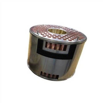
3. Fin Geometry and Efficiency
Fin design plays a key role in system efficiency. Closely spaced fins offer high heat transfer but may trap soot and increase pressure drop. Wider spacing improves cleanability but slightly reduces surface area. The fin geometry must be optimized for the specific generator exhaust conditions.
4. Tube and Fin Material
The materials used for the tubes and fins affect both heat transfer and durability. Common materials include carbon steel, stainless steel, and copper alloys. Stainless steel offers superior corrosion resistance at high temperatures, while copper fins provide excellent thermal conductivity.
5. Gas and Fluid Velocity
Flow velocity influences turbulence and heat transfer rate. Higher velocities improve performance but also raise pressure drop and fan power consumption. Balancing these factors ensures effective operation without excessive energy loss.
6. Fouling and Soot Formation
Soot and particulate buildup on the fin surfaces create an insulating layer that significantly reduces heat transfer. Regular cleaning and proper filtration are essential to maintain efficiency. Systems operating on natural gas typically experience less fouling than those using heavier fuels.
7. Temperature Difference (ΔT)
The temperature difference between exhaust gas and the heat recovery fluid (usually water or thermal oil) is the main driving force for heat transfer. Greater ΔT results in more efficient energy recovery. Counterflow designs generally maintain a higher average temperature difference compared to parallel flow.
8. Flow Configuration
Counterflow heat exchangers, where gas and fluid flow in opposite directions, offer higher thermal performance than parallel-flow systems. This design maximizes the usable temperature difference and ensures more uniform heat transfer.
9. Pressure Drop Considerations
While increasing heat transfer surfaces can improve recovery, it may also lead to higher pressure drops. Excessive back pressure on the generator exhaust reduces engine efficiency. Therefore, an optimal balance between heat recovery and acceptable pressure loss must be maintained.
10. Maintenance and Operation
Regular inspection, cleaning, and performance monitoring are crucial for maintaining consistent heat recovery. Well-maintained finned tube systems can operate efficiently for many years with minimal performance degradation.